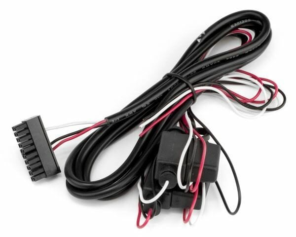
GPS AnyPlace Wiring Harness
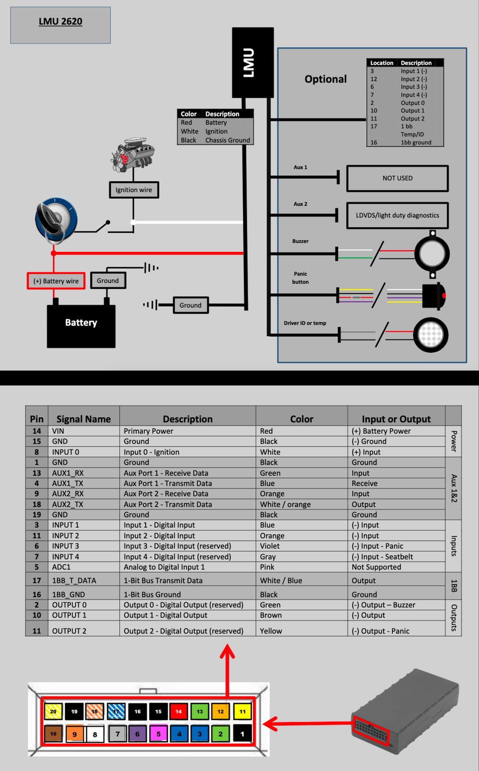
The relay is pre-wired for you. All you need to do is insert the pin on the yellow wire to the 4th pin position in the wiring harness on the GPS device. It would be the 4th position from the left. It is the pin slot next to the red, black and white wires already in the harness.

GPS AnyPlace Wiring Harness Details
Tracking System GPS AnyPlaceTechnical Support and Instructions. If you need further assistance please call Gary at (313) 402 0700, or for IT support please contact Robin on (813) 419 4382

At GPS AnyPlace, we offer a premium wiring harness solution designed for hassle-free installation and optimal performance of your GPS device. Our pre-wired relay ensures quick setup with minimal effort—simply connect the yellow wire pin to the 4th pin slot in the harness, and you're good to go. With clear instructions and a reliable connection to the red, black, and white power lines, you'll have your GPS device up and running in no time. Our wiring harness simplifies the process, so you can focus on what matters: keeping your vehicles and assets tracked and secure. Upgrade your GPS installation today with our professional-grade wiring harness for a smooth and efficient experience!
"At GPS AnyPlace, we believe in delivering cutting-edge GPS solutions that keep you connected, secure, and in control—wherever life takes you. Our reliable tracking technology and seamless installation process ensure peace of mind, knowing your assets are always within reach."
— GPS AnyPlace Team
"At GPS AnyPlace, we believe in delivering cutting-edge GPS solutions that keep you connected, secure, and in control—wherever life takes you. Our reliable tracking technology and seamless installation process ensure peace of mind, knowing your assets are always within reach."
— GPS AnyPlace Team

.
Wiring Harness
A wiring harness is used to organize and connect multiple electrical wires within a system, efficiently transmitting power and signals between components while simplifying installation and reducing the risk of electrical faults.
Pin and Input/Output Information
| PIN Number | Input/Output |
|---|---|
| PIN # 4 | INPUT # 1 |
| PIN # 5 | INPUT # 2 |
| PIN # 6 | INPUT # 3 |
| PIN # 7 | OUTPUT # 1 |
| PIN # 8 | OUTPUT # 2 |
| PIN # 9 | BATTERY BACKUP LOOP |
| PIN #14 | BATTERY BACKUP LOOP |

Do You Have Questions?
If you have additional questions we encourage you to contact us for more information.
